IO Port
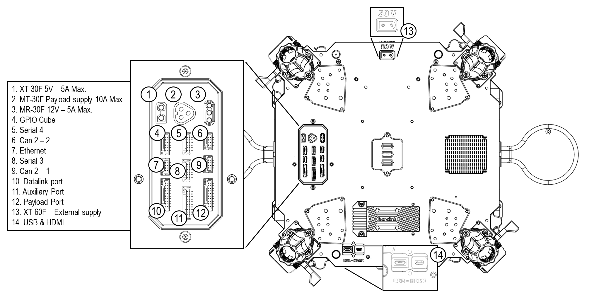
The bottom plate of the Hercules has several easily accessible ports that allow you to connect different additional peripherals through specific protocols to the autopilot. The total available interfaces for each protocol type are summarized below:
XT-30F (5V-5A max)
| #PIN | NAME | I/O | VOLTAGE | OBSERVATIONS |
|---|---|---|---|---|
| 1 | GND | - | GND | - |
| 2 | VCC-5V | Out | 5V | 25 W max. |

Connector Amass XT-30F
MT-30F (Payload Supply, 10A max)
| #PIN | NAME | I/O | VOLTAGE | OBSERVATIONS |
|---|---|---|---|---|
| 1 | Vcc dedicated regulator | Out | 12 v / 24 v / 30 v | 100 W max. |
| 2 | GND | - | GND | |
| 3 | NC | - | - |

Connector Amass MT-30F
MR-30F (12V - 5A max)
| #PIN | NAME | I/O | VOLTAGE | OBSERVATIONS |
|---|---|---|---|---|
| 1 | GND | - | GND | 60 W max |
| 2 | VCC-12V | - | 12V | |
| 3 | NC | - | - |

Connector Amass MR-30F
GPIO CUBE
| #PIN | NAME | I/O | VOLTAGE | OBSERVATIONS |
|---|---|---|---|---|
| 1 | VCC-5V | Out | 5V | 1A maximum load |
| 2 | AUX OUT1 | Out | 3.3V | PWM auxiliar signal connected to FMU_CH1_PROT |
| 3 | AUX OUT2 | Out | 3.3V | PWM auxiliar signal connected to FMU_CH2_PROT |
| 4 | GND | - | - | GND |
| 5 | SBUS 2 | Out | 3.3V | RCIN – Signal PPM/SBUS |
| 6 | GND | - | - | GND |
Connector Information
- Connector JST-GH 1.25mm – 6 circuits
- Contact: SSHL-002T-P0.2
- Housing: GHR-06V-S
- Receptacle: BM06B-GHS-TBT

Serial 4 (from the flight controller)
| #PIN | NAME | I/O | VOLTAGE | OBSERVATIONS |
|---|---|---|---|---|
| 1 | VCC-5V | Out | 5V | 3A maximum load |
| 2 | MCU-TX4 | Out | 3.3-5V TTL | Tx from flight controller |
| 3 | MCU-RX4 | In | 3.3-5V TTL | Rx from flight controller |
| 4 | NC | - | - | N/A |
| 5 | NC | - | - | N/A |
| 6 | GND | - | GND |
Connector Information
- Connector JST-GH 1.25mm – 6 circuits
- Contact: SSHL-002T-P0.2
- Housing: GHR-06V-S
- Receptacle: BM06B-GHS-TBT
CAN2 - 1 & CAN2 - 2 (from flight controller)
| #PIN | NAME | I/O | VOLTAGE | OBSERVATIONS |
|---|---|---|---|---|
| 1 | VCC-5V | Out | 5V | 1A maximum load |
| 2 | CAN-H | In/Out | 12V | CAN-High |
| 3 | CAN-L | In/Out | 12V | CAN-Low |
| 4 | GND | - | GND | - |
Connector Information
- Connector JST-GH 1.25mm – 4 circuits
- Contact: SSHL-002T-P0.2
- Housing: GHR-04V-S
- Receptacle: BM04B-GHS-TBT

ETHERNET (Dedicated port)
⚠️
Only for Doodle labs telemetry version
- Virtual Ethernet port
- USB interface is required when used
| #PIN | NAME | I/O | VOLTAGE | OBSERVATIONS |
|---|---|---|---|---|
| 1 | NC | - | - | |
| 2 | USB D- | In/Out | Diff signal | Ethernet Only |
| 3 | USB D+ | In/Out | Diff signal | Ethernet Only |
| 4 | GND | - | - |
Connector Information
- Connector JST-GH 1.25mm – 4 circuits
- Contact: SSHL-002T-P0.2
- Housing: GHR-04V-S
- Receptacle: BM04B-GHS-TBT
Serial 3 (from the flight controller)
| #PIN | NAME | I/O | VOLTAGE | OBSERVATIONS |
|---|---|---|---|---|
| 1 | VCC-5V | Out | 5V | 1A maximum load |
| 2 | MCU-TX3 | Out | 3.3-5V TTL | Tx from flight controller |
| 3 | MCU-RX3 | In | 3.3-5V TTL | Rx from flight controller |
| 4 | NC | - | - | N/A |
| 5 | NC | - | - | N/A |
| 6 | GND | - | GND |
Connector Information
- Connector JST-GH 1.25mm – 6 circuits
- Contact: SSHL-002T-P0.2
- Housing: GHR-06V-S
- Receptacle: BM06B-GHS-TBT
Datalink Port
| #PIN | NAME | I/O | VOLTAGE | OBSERVATIONS |
|---|---|---|---|---|
| 1 | 12V | Out | 12V | 12V power output for datalink. 1A max. load |
| 2 | Program ESC 8 | In/Out | - | Serial telemetry line from ESC |
| 3 | Program ESC 7 | In/Out | - | Serial telemetry line from ESC |
| 4 | Program ESC 6 | In/Out | - | Serial telemetry line from ESC |
| 5 | Program ESC 5 | In/Out | - | Serial telemetry line from ESC |
| 6 | Program ESC 4 | In/Out | - | Serial telemetry line from ESC |
| 7 | Program ESC 3 | In/Out | - | Serial telemetry line from ESC |
| 8 | Program ESC 2 | In/Out | - | Serial telemetry line from ESC |
| 9 | Program ESC 1 | In/Out | - | Serial telemetry line from ESC |
| 10 | GND | - | GND |
Connector Information
- Connector JST-GH 1.25mm – 10 circuits
- Contact: SSHL-002T-P0.2
- Housing: GHR-010V-S
- Receptacle: BM10B-GHS-TBT

Auxiliar Port
| #PIN | NAME | I/O | VOLTAGE | OBSERVATIONS |
|---|---|---|---|---|
| 1 | S9 | In/Out | - | General purpose signal |
| 2 | S8 | In/Out | - | |
| 3 | S7 | In/Out | - | |
| 4 | S6 | In/Out | - | |
| 5 | S5 | In/Out | - | |
| 6 | S4 | In/Out | - | |
| 7 | S3 | In/Out | - | |
| 8 | S2 | In/Out | - | |
| 9 | S1 | In/Out | - | |
| 10 | GND | - | GND |
Connector Information
- Connector JST-GH 1.25mm – 10 circuits
- Contact: SSHL-002T-P0.2
- Housing: GHR-10V-S
- Receptacle: BM10B-GHS-TBT
Payload Port
⚠️
Pins 1, 2, 3, 4, Only for Doodle Labs Telemetry version. Connected to ETH0 in Doodle Labs modem Pins 5, 6, 7, Only for Hyspex Edition
| #PIN | NAME | I/O | VOLTAGE | OBSERVATIONS |
|---|---|---|---|---|
| 1 | DL TX- | In/Out | - | Doodle Labs Ethernet port |
| 2 | DL TX+ | In/Out | - | Doodle Labs Ethernet port |
| 3 | DL RX- | In/Out | - | Doodle Labs Ethernet port |
| 4 | DL RX+ | In/Out | - | Doodle Labs Ethernet port |
| 5 | ADQ | - | - | acquisition pin for Mjolnir |
| 6 | 5V - FOCUS | - | - | acquisition pin for Mjolnir |
| 7 | GND ADQ | - | - | acquisition pin for Mjolnir |
| 8 | NC | - | - | Not connected |
| 9 | NC | - | - | Not connected |
| 10 | GND - Drone | - | GND | GND drone different from pin 7. |
Connector Information
- Connector JST-GH 1.25mm – 10 circuits
- Contact: SSHL-002T-P0.2
- Housing: GHR-10V-S
- Receptacle: BM10B-GHS-TBT
EXTERNAL 50V
⚠️
- This port is directly connected to the Battery Input. This is not a 50V regulated voltage
- Power Capacitor inside
| #PIN | NAME | I/O | VOLTAGE | OBSERVATIONS |
|---|---|---|---|---|
| 1 | GND | - | - | Directly connected to main Battery Power |
| 2 | V Batt | Out | ≈50V | Varies with flight time. (43v - 51v) |
